 Table of Contents Watch What I Do
A particular problem solving domain is considered here -- Euclidean geometry. In this domain, the objects of concern are points, lines, and circles, and relationships in this realm are spatial; for example, "perpendicular to," "at the intersection of," and "with radius equal to." We explore the process of expressing geometric relationships visually and by demonstration. We call this process "sketching" and develop through it a notion of "spatial programming."
The specific application considered here is The Geometer's Sketchpad[1], an environment for exploring geometry now being used in thousands of high school mathematics classrooms. The primary purpose of GSP's ongoing development is the resolution of real-world issues surrounding the learning of geometry. It is surprising to find that this practical focus leads to a theoretically interesting conception of users programming by demonstration. Because in GSP there is no distinction between the geometric content domain and the spatial programming domain, students using it encounter programming as the central activity. The distinction between programmer and user disappears; the two coalesce into one -- the student.
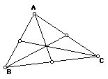
Draw a triangle. Place a point at the midpoint of each side. Connect the midpoints to the vertices opposite them, forming medians. The sketch looks something like that shown in Figure 1. Notice that the three medians appear to pass through a single point. Is this always true? One would like to investigate this conjecture -- that the medians of a triangle intersect at a common point -- without having to start from scratch with a new sketch. The original sketch should embody the desired relationships between points and lines so that the sketch can be dynamically modified and the relationships kept intact. GSP provides this capability.
A
triangle drawn in GSP is an example triangle -- one of an infinite
number of possible triangles. The sides of the triangle are implicitly
constrained to be connected to each other at the vertices. Using a menu
command, one explicitly constructs the midpoint of each side. Finally,
the medians are constrained to always connect vertex and opposite midpoint,
again as an implicit relationship asserted through the act of drawing lines.
The components of the resulting sketch can be dragged and the desired
relationships will remain intact.

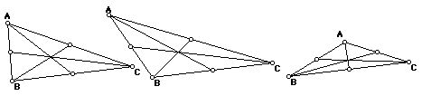
Figure 2 shows the result of dragging one of the vertices to several different points. The conjecture that the three medians are coincident appears to hold in each of the additional cases. On the computer screen, while dynamically dragging the vertex, one sees that the conjecture holds for a very large number of triangles. This convincing visual demonstration is not a proof of the conjecture. There may be a lack of coincidence at a resolution below that of the screen, or there may be a special case triangle that was not examined. In many situations, one is led naturally to wonder why a particular conjecture should be true or to search for a counter-example; that is, one is drawn into the process of proving or disproving the conjecture.
A few technical definitions will be helpful. All objects in GSP live in a dependency diagram, a directed acyclic graph. The "given" objects in a construction (such as points A, B, and C in the preceding example) are "free nodes;" i.e. no arcs point to such nodes. Objects that are constrained in some fashion, such as the midpoints of the sides of the triangle, are "dependent nodes." They are "children" of the objects on which they depend -- their "parents." A sketch consists of one or more sets of objects held together by a system of constraints. Figure 3 depicts the internal constraint representation of the construction of Figures 1 and 2. Students using GSP acquire an informal understanding of some of these terms, especially free, parent, and child. More importantly, they come to understand how a geometric construction can be defined by a system of dependencies.
The remarkable characteristic of GSP's system comes from the realization that a program's structure -- i.e. its "source code" -- and its output are isomorphic. When the student completes the specification, or coding, of the centroid construction in the above example, he or she has at the same time located a specific centroid. By manipulating the vertices of the triangle (the program's inputs), the student generates further output. Significantly, these manipulations are performed in the same domain, that of planar geometric objects, as the act of constructing the initial sketch.
This visual identity between a program and its output defines for us the term spatial programming, and differentiates a student's activity in GSP from other interactive constraint-solving systems. While a spreadsheet can be programmed by demonstration, if valid data are initially entered into the cells before "programming" other cells with arithmetic relationships, the domain and mechanism of programming -- specifying formulae -- are distinctly separate from that of the program's input and output. (Most spreadsheets today make this distinction clear in their interface; in which one types and reads data directly in the cell matrix, but enters a special-purpose and modal editor when specifying cells' arithmetical productions.) In contrast, in GSP, the program and its output are identical, and the student's experience is thus not clearly divided into specification and execution modes; there is no tangible distinction between programmer and user.
In the centroid example of Figure 1, the entire structure of the program is
exoskeletal: all of its components contribute equally to the program's visual
output. As the size of a program, or GSP activity, increases, the need for data
privatization and logical encapsulation grows rapidly more apparent. (A
large-scale system is most efficiently engineered by coordinating black-boxed
subsystems.) GSP addresses these needs in a primitive fashion by allowing
components of a construction to be selectively hidden from view, without
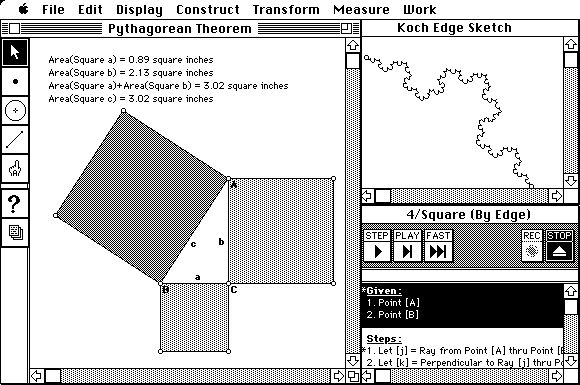
affecting their geometric determination of other objects. Figure 4 shows hidden
elements used to construct a square. The circle ensures that
 =
= .
The lines
.
The lines
 and
and
 are constrained to be perpendicular to
 while the line
 is constrained to be parallel to
 .
These auxiliary elements are hidden to focus attention on the important visual
output of the sketch, the square itself.
.
These auxiliary elements are hidden to focus attention on the important visual
output of the sketch, the square itself.
In addition to directing visual focus, hidden elements of a sketch allow synthesis of meta-constraints -- composite behaviors linking visible parental objects to child objects. Figure 4, with circle and lines hidden, demonstrates a meta-constraint relating two independent points (A and B) to the square on their side. In that any construction, or portion of a construction, can be duplicated by the Macintosh's copy-and-paste mechanism, the square program demonstrated here can be replicated and re-used to generate all future squares. Recycling one's previous work in new contexts provides a rudimentary form of subroutine (in this example: a function returning a square given two point parameters). In that GSP objects serve as both control and data, the hidden objects in a function parallel a subroutine's locally-scoped code and state.[2]
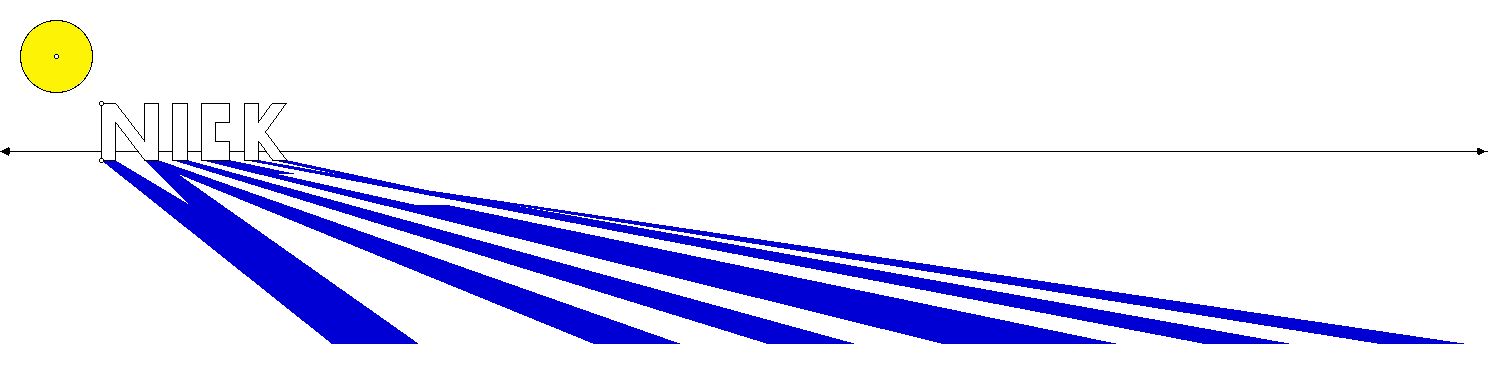
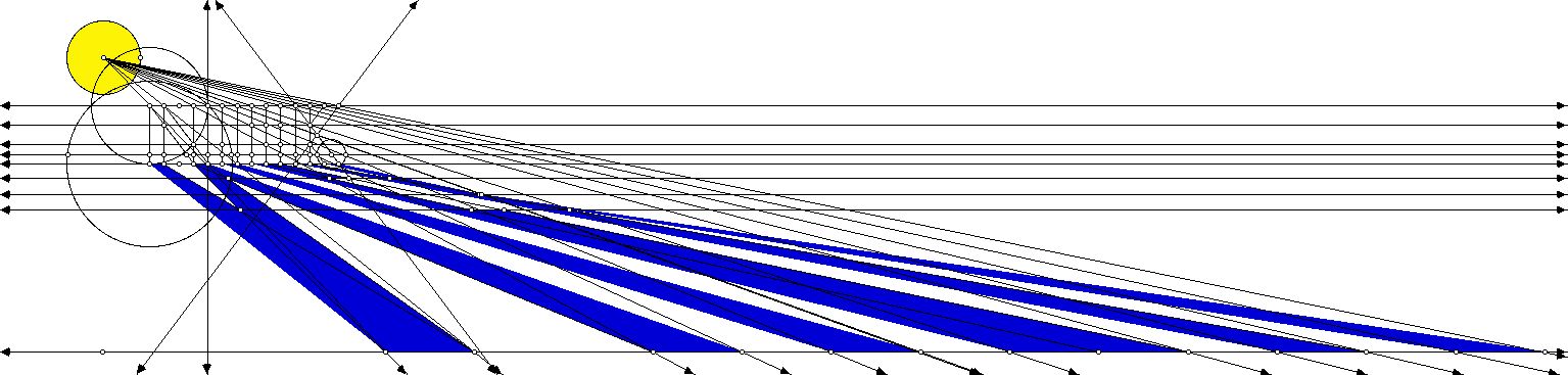
In practice, meta-constraints afforded by duplicating constructions (with intermediate hidden objects) allow precisely the sort of scalability traditionally associated with modular code and static scoping. Figure 5, which illustrates shadow-projection, contains over 150 distinct components. In its construction, however, the author manually specified the relation between a pre-image vertex and its shadowed image only once. This relationship, which contains hidden objects (a ray projecting from the light source to the preimage; a base-line for the 2D representation of the plane's normal), was then encapsulated as a function (using a mechanism described in more detail below), and subsequently applied to the other vertices of the preimage. By defining a new meta-constraint, the author moved from a cognitive arena ruled by compass-and-straightedge construction to one governed by a model of ray-tracing and the manipulation of light. By building and using such abstracted spatial functions, students may scale the domain of potential applications while keeping complexity relatively constant.
Reversible primitives allow students to drag the children, or dependent nodes, of a construction, with GSP automatically recalculating new positions for the parents. This increases the flexibility of a construction, and in doing so, vastly broadens the notion of "input" in a GSP "program." Having constructed a model of forward-chaining logic, one can then reverse the directionality of the system, and reason from desired output to the input necessary to generate such output. If spreadsheets allowed such reversible constraints, a user, having programmed corporate profit as a function of cost, sales, and volume, could enter a desired profit and then review "output" business scenarios leading to that profit.
Consider the utility of reversible program logic by extending the investigation depicted in Figure 1. Having manipulated the vertices of a triangle and begun to formulate conjectures about its centroid, a student might ask: "what is true of a triangle when its centroid coincides with its circumcenter?" Under a traditional, forward-reasoning programming model, one would have to describe a function that mapped two points (a centroid and a circle's center) to a triangle -- not a straightforward compass and straight-edge construction. In GSP, the question can be approached in reverse, by constructing a circle, inscribing in it a triangle, and locating the centroid of the triangle. Figure 6[left] illustrates such a construction. The centroid of this triangle -- a logical output of a complex program taking the initial circle as input -- can then be dragged coincident to the circle's center (as in 6[right]), demonstrating the fact that circumcenters and centroids are coincident in equilateral triangles.
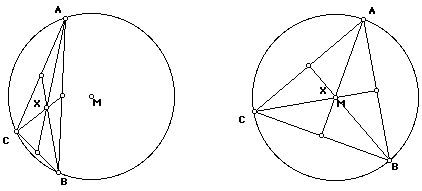
A number of GSP's constraints have no unique mapping when reversed. A segment determines its midpoint, for example, but a midpoint does not uniquely determine a segment. (An infinite number of segments share a single midpoint.) Rather than bar motion on the products of such constraints, we provide heuristically-chosen reverse functions. Given motion on a midpoint, for instance, GSP attempts to preserve the length and slope of the midpoint's parental segment. In the figure above, motion on the intersection centroid is reversed into parallel motion on its intersecting parents (the medians), which is then tempered by the constraint on the medians' vertex parents (that they lie on the circle). In that these heuristics limit the search space in well-defined ways, it is important to realize that a solution presented by an inverted program is but one of perhaps many. Nonetheless, the ability to drive logic backwards greatly enhances the problem-solving capacity of a spatial program.[3]
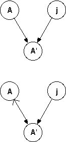
The internal mechanism that allows one to drag constrained objects is the topological sort used to determine an evaluation order for all graph nodes (objects) affected by a transformation. In a static state, the graph which represents a sketch describes a single geometric relation between a child and its parents as the set of arcs leading to the child node. Figure 7[top] illustrates a subgraph relating Point A' to both Point A and Line j, as it might appear -- for instance -- if A' was the reflection of A in the mirror j. GSP extends conventional graph notation to include a reversible arc. This arc represents a bidirectional constraint, and has both a primary direction (represented by a dark arrow head in 7[bottom]) and a secondary direction (represented by the lighter arrowhead).
The primary direction of a reversible arc indicates the logical dependency of the construction: A' is the child of A and j. During dragging, however, the secondary direction of the arc will be considered if A' is encountered in the node tour before either of its parents. In this case, the liberty of A' to be dragged is deferred onto A (by the secondary direction of arc AA'); that is, A' can be dragged if we can find a new location for A (and A itself is not overconstrained). Essentially, we are dynamically (and temporarily) reordering the graph, as if shaking a tree by a leaf to form a new tree, in which the former leaf is now root. From the student's point of view, GSP behaves as if it were solving its non-linear constraints simultaneously, but with the speed associated with a linear programming solution.
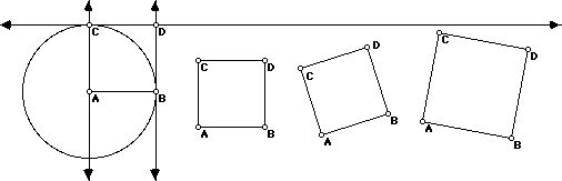
 to equal
 is not constrained to pass through B at all. (The query tool reveals
this problem by giving the definition of the circle.) The drawing -- and the
geometric steps that lead to it -- is not a valid construction of a square.
is not constrained to pass through B at all. (The query tool reveals
this problem by giving the definition of the circle.) The drawing -- and the
geometric steps that lead to it -- is not a valid construction of a square.

Gradually students come to appreciate the difference between a drawing and a construction. A proper construction maintains the desired relationships between objects no matter how it is dragged. At the same time, a good construction allows maximum flexibility in its dragging of components so that as many ramifications of the construction as possible can be explored.
In that all states of the program are continuously present and examinable, and that all logical linkages in a sketch transform simultaneously, debugging a sketch involves reasoning directly from the manifestation of a bug backwards, along the dependency relationships -- toward its cause. By contrast, in a sequential programming model, one locates the source of such a bug circuitously. Once buggy output is reproducible, one re-executes the program, usually with some form of breakpoint at an arbitrary state prior to the manifestation (symptom) of the bug. Should this break-point state itself prove buggy, one re-executes again, with an earlier breakpoint. If the initial breakpoint state is "clean," one moves the breakpoint forward, closer to the symptom. By this trial-and-error process, one eventually closes in on the symptom's cause. Comparatively, debugging a sketch is far more direct. In that GSP does not rely on a sequential, one-way execution model, one can reason directly from the symptom back to the cause, without navigating extraneous states located prior to the bug's source or between its source and symptom.
Assertions in Prolog are made through textual statements of facts or rules such as the following: likes(joe,fish).
parent(joe,mary).
sister_of(X,Y) :-
female(X),
parent(P,X),
parent(P,Y). GSP assertions are made by applying spatial constraints during construction of objects. Expressed as text, these constraints might appear as: Let point A be the intersection of lines x and y.
Let point B be a random point on circle 2.
Let m be the line perpendicular to segment j through point A. Queries in Prolog allow the user to ask for ways to satisfy certain constraints. They are expressed textually as in, for example, sister_of(S,mary). Responses come back as a list of solutions: S=jane; S=samantha. In GSP, the student queries by dragging some component or components of the sketch. The student is asking the program to show geometric solutions to the problem posed by the imposed constraints. These solutions are displayed continuously during the dragging operation. If there are no solutions, Prolog responds by saying "no," while GSP responds with an alert explaining why the selected objects cannot be dragged.
Both Prolog and GSP have similar notions of reversible relationships.
The student can query parent(P,mary), parent(mary,C), or even
parent(P,C). In GSP, the student can ask for solutions by dragging
children of the free nodes, with GSP computing new positions for the parents.
For example, the line segment
 in the triangle shown in Figure 1 can be dragged, and GSP will compute new
positions for points A and C.
in the triangle shown in Figure 1 can be dragged, and GSP will compute new
positions for points A and C.
Prolog and GSP are not totally comparable. Prolog, through use of backtracking, can offer multiple solutions to given constraints while GSP can only offer one. Prolog has an implicit dependence on order -- those facts and rules that appear first in the database are used first in searching for solutions. GSP has no dependence on order of specification at all. Furthermore, because GSP is embedded in a content domain, it is able to generate meaningful explanations for occurrences such as the inability to drag multiple objects with constraints that cannot be simultaneously satisfied.
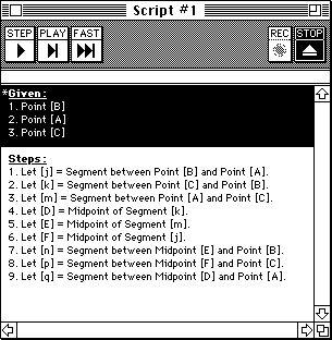
A visible sketch is always an example of output from the generalized construction implied by the diagram's constraints. In a separate view -- the script -- one can examine a sketch's constraint system in verbal form, untied from its coordinatized instantiation. Figure 9 illustrates a script describing a triangle's medians. Any construction can be viewed as sketch or script.[4]
Note the script's divisions into Givens and Steps. The former section describes the logically autonomous (unconstrained) components of a construction; the latter, the various dependencies built upon these given components. The language of description corresponds to the vocabulary of geometry texts. At any point, a script may be "played" onto new given objects, recreating the system of constraints (most likely in a new coordinate configuration). The "triangle with medians" script takes three points as input and produces a sketch in which the three points are connected to each other and to the midpoints of the opposite sides. Although scripts and sketches describe identical phenomena -- a construction from different viewpoints -- scripts, functioning as macros or subroutines, are invaluable aides to the construction process.
While the equivalence of the dual representations of sketch and script is to be stressed on a theoretical level, the respective interface expressions clearly present distinctions. Statically, sketches entirely emphasize output, and dynamically, they emphasize mechanism, with constraints appearing under the course of transformation as pseudo-mechanical linkages. However, manifestations of order of dependency or "logic path" are virtually absent from a sketch: there is no visible distinction between free nodes and highly-constrained nodes, and the presence of reversible relationships (as described earlier) diminishes the notion of a single rigid and unidirectional "chain-of-being" stratifying the sketch's objects.
Scripts, on the other hand, describe exactly the set of dependencies relegating some objects to others, and divide the construction clearly into independent and dependent objects; that is, parameters and output. Precisely because they avoid visualizing the relationships in the specific instance (or set of instances, over time) represented by a sketch, scripts can not only generalize a drawing to the construction of all related drawings, but it can also describe itself self-referentially and abstractly.
Abstraction, in a script, specifically uses meta-objects to relax the strongly-typed image of a construction represented by a single sketch. For example, if one of the parameters of a specific sketch is a segment, and yet only the slope of that segment and not its finite length is significant to the remainder of the construction, the scripted representation of that sketch's construction will refer to a given straight object, as opposed to a given segment. During the script's playback, the student can instantiate that parameter with a line, a ray, or a line segment, all of which satisfy GSP's notion of a straight object. While this variety of abstraction yields a more versatile script, it is worth noting that in the visual vocabulary of a sketch, the abstract "straight object" does not exist.
Self-reference allows a script to describe a recursive program accurately, opening the door in geometry classes to many families of fractal. A "Loop" button is used to specify a recursive relationship between the parameters (given objects) of a script and a subset of its output (produced objects). Such a relationship characterizes a construction as self-similar. The actual depth of recursion used when rendering the script in a sketch is determined by the user (and available RAM) during playback. Figure 10 shows the script for a simple fractal, along with the result of playing the script on an existing triangle to three stages of recursion. Again, the script's verbal form -- with its implication of bottomless recursion and infinite self-similarity -- represents the construction in a more analytically precise manner than the necessarily approximate rendition of the sketch. Scripts better describe the ideal prototype of a construction, but sketches -- being a limitlessly reworkable example -- much more readily convey the behavior of a system.

Consequently, we seek to continue reducing the perceived separation between sketch and script, in order to test whether this difference in usage is related to the software-specific predilection for sketches (i.e. you are first confronted with a sketch, not a script; the program is "a sketchpad," not "a scriptpad"). If not, we would argue that mastery of the traditional, sequential or procedural programming model represented by scripts involves an inherently higher degree of cognitive complexity than the functionally equivalent approach to problem solving that we call spatial programming. Our tentative hypothesis is that spatial programming is more intuitive and just as expressive as procedural programming.
Should this hypothesis prove correct, the next question becomes: in what other areas can one conceive of a spatial programming solution? Obviously, planar geometry is well suited to this particular form of demonstrative constraint programming. We would like to explore and extend the application of spatial programming to domains such as CAD, spreadsheets, flowcharting, and project management. The importance of heuristically-governed reversibility is tantamount here, providing the mechanism that could transform a spreadsheet's traditionally linear unit-cost-to-profit model into one capable of answering a much wider range of user inquiry. In this light, the analogy to logic programming should be further explored and exploited. Backtracking, as implemented by Prolog, may have application to spatial programming, in that it could generate multiple heuristically-determined solutions to a constraint set, rather than the solitary one now provided by GSP.
Intended users: Students
Table of Contents Watch What I Do