 Table of Contents Watch What I Do
Triggers is a programming system that shows how simple pattern matching applied to the pixels on a computer screen can effectively access data that is otherwise hidden inside an application program and unavailable to other programming by demonstration systems. Triggers invokes operators in applications by simulating keyboard and mouse actions, and accesses data through the pixel representations on the computer screen. Triggers extends the record/playback style popularized by keyboard macros. Triggers shows that pixel-based device-level algorithms exist, are understandable, can be easily implemented, and can allow a programming system to process data in situations where it would otherwise be impossible.
The Triggers programming system is part of an ongoing research project to show how simple pattern matching on the pixel representations in the computer display buffer can significantly enhance a programming system's ability to access data. Because pixel representations are low-level, the algorithms that make use of this representation are different from what one would expect for a given task. Triggers demonstrates that these algorithms exist, are understandable, accomplish useful tasks, and can be easily implemented.
Pixel-based data access seems to run counter to the widely acknowledged fact that high-level data and constructs improve programming productivity. Unfortunately, this fact has led to widespread acceptance of a conclusion that, strictly speaking, does not logically follow: that programming with low-level data and operators is inherently inefficient. This research shows that the inherent visual nature of pixels, the high degree of regularity of modern graphical user interfaces, and the user's extensive familiarity with the display content make programming at the pixel level appropriate.
Programming systems can process data that the user creates with applications using two main strategies. One is to process the data separately from the application (Figure 2). First the programming system must obtain a copy of the data from the application, perhaps through the file system or a paste buffer. Then the user's program processes the data. The advantage of this approach is that the programming system has a private copy of the data and can process it with much speed and flexibility.
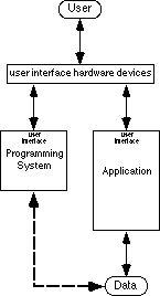
Processing data separately from the applications also has several disadvantages. One is that often the data produced by an application is so richly encoded that the user cannot justify learning how to write an algorithm sophisticated enough to process it. If the user expects to return the results of the processing back into the application for further manual processing then the algorithm must also output data in the application's coded format. Another problem is that the overhead of exporting data from the application and importing the data back into the application can undermine the benefits of automating.
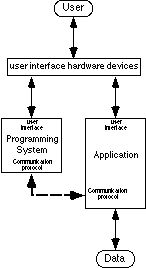
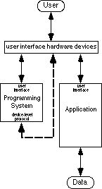
The techniques described in this chapter are a special case of the second strategy which is to process the data by manipulating the application. For this strategy, the user's programming system invokes operators (features) of the application in an order that achieves the desired automation and thus processes the data indirectly. In terms of data access, this strategy merely transforms the data access problem to another form (Figure 3). Now the user's challenge is to have the programming system invoke operators of the application. The programming system must also be able to access data within the application if algorithms with conditionals and loops are to be possible.
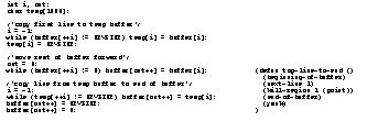
An algorithm that processes data within an application takes on a form different from that of an equivalent algorithm in a language like C. For example, two algorithms that move the top line of a buffer to the end of the buffer appear in Figure 4. Notice that the elisp algorithm avoids all the looping constructs required in the C algorithm by building on the special functionality of Emacs. In effect, the execution environment of the program has partially changed from the stacked activation records and global variables of a traditional programming language, to the document of the application.
Because the operators and data of these algorithms often appear in the user interface of the application, algorithms take on a form that the user can demonstrate with the user interface of the application. Thus much of the research discussed in this book addresses the data access obstacle by embedding programming systems within applications. This body of research, however, mostly waives the logistics of how a programming system invokes operators and accesses data in an application in order to concentrate on user interface issues.
Another way to effect this protocol is by establishing a protocol especially for interapplication communication. Any programming system and application that both follow the standard protocol can then communicate, allowing the programming system to manipulate the application. Apple Events in System 7 on the Macintosh is an effort in this direction [Apple 91]. Applications and programming systems that follow these protocols are just becoming available.
Figure 4. Two algorithms that move a line of text from the beginning of a buffer to the end. The left algorithm is in C and assumes the buffer is an array. The right algorithm is in elisp and assumes the buffer is an Emacs buffer.
There
are times when these protocols are the weak link to achieving data access. As
is the case today, sometimes the standard protocols are too new and few
applications follow them. Sometimes the protocol is not extensive enough to
access the specific piece of data that needs to be accessed. Still, because
these protocols are specially designed for interprocess communication, they
represent a necessary step forward in allowing programming systems to
efficiently access data within applications.
Many commercial systems have taken advantage of this protocol in the form of keyboard macros. Keyboard macros basically work by simulating the algorithmic actions of the user at the keyboard. In theory, any operator that the user can invoke from the keyboard can be invoked by a keyboard macro program.
Compared with how easy they are to implement, keyboard macro systems add a surprising amount of power. Adding merely a keystroke recorder and a playback mechanism, designers can include a significant degree of programmability into their software systems. When placed inside a functionally rich application, macros can automate some surprisingly sophisticated tasks, even though the macro mechanism itself has no domain knowledge other than that of the keyboard input stream. When implemented as part of the operating system, the utility of the keyboard macro is automatically inherited by all the applications of the operating system. Probably for these reasons, keyboard macros can be found in applications as diverse as operating systems, word processors and spreadsheets. They are a good investment. With the advent of graphical user interfaces, keyboard macros have been extended to also simulate the user's interactions with the mouse.
Unfortunately, users often find that macros are very sensitive to the state of an application and thus too fragile. For example, the keypress "y" can have drastically different semantics depending on whether the system is accepting a file name or waiting for the response to a "yes/no" prompt. These limitations are accentuated in graphical user interfaces where time and screen location are important factors. The semantics of a mouse click can depend on time, because some user interface artifacts, like dialog boxes, can be transient. The semantics of a mouse click also change as icons and windows are moved about the computer display. These problems are so severe that purely device-level keyboard/mouse macros are practically useless for graphical user interfaces.
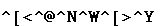
Algorithms for keyboard macros are drastically different from algorithms in traditional programming languages or algorithms that control applications through formal protocols. For example, the algorithm in Figure 6 does the same line-moving task as the algorithms in Figure 4. The algorithm is simply what the user would type if accomplishing the task manually. Raw keystrokes in isolation are very cryptic and contain very little semantic content. This has led to the popular explanation that keyboard/mouse macros are limited because they interact on too low a level [Halbert 84][Cypher 91a].
A more telling reason for the limitations of device-level keyboard/mouse macros is that, as a programming system, their input/output is almost exclusively output. In other words, operators are invoked, but data is not accessed. Here the simulating of user actions breaks down because the algorithms can not observe the state of the application to decide appropriate actions. Without data access, only straight line algorithms are possible because conditionals and loops have no basis to make logical tests.
In short, keyboard macros are a mixed success in terms of overcoming the data access obstacle. They are remarkably good at directing the processing of data residing in diverse applications, but they are severely limited by a data access problem of their own. They can process the data by invoking operators in the application, but they can not access enough information to support more than the simplest of algorithms.
Researchers and commercial products have explored various ways to avoid the need for data access. The simplest has been to include time delays into macros. Rather than test for a certain condition being true, like the appearance of a dialog box, these macros simply include a time delay that hopefully ensures that the condition becomes true before playback of the macro continues.
Some macro systems have abandoned the purely device-level approach by recording information from the operating system into the macro. For example, suppose the user clicks on a check box to turn it on. Check boxes are often implemented as toggles, so a simple replay of the mouse click would toggle the setting, and not set it as the user intended. A macro system utilizing information from the operating system records that the click set a particular check box. When the macro is replayed, the macro system locates the particular check box and sets it by manipulating the operating system.
Higher-level constructs have many advantages as discussed in Chapter 22, but they also have a cost. Macros lose the simplicity that made them an easy addition to most any software system because the semantics of every operation in the user interface has to be integrated into the macro system. The complexity to the user can increase because the user must be aware of how the macro system interprets these semantics. For example, if the user actually wanted to toggle the check box, the higher-level semantics could interfere.
Others have researched the merits of programming systems that emphasize data in pixel form. Scott Kim noted that the pixel representations on a computer display are secondary representations of data structures hidden in the computer [Kim 88]. He asked whether the roles could be reversed and the visual pixel representation could become the primary data structure. His text editor VIEWPOINT showed that a system was possible where all state information is represented visually in pixel form. He defined the principle of visibility to encapsulate this ideal. He goes on to discuss many other elegant ideas about pixel based computing.
George Furnas created a system called BITPICT that manipulated a matrix of pixels that served as a blackboard of a production system [Furnas 91]. Each rule in the production system searches for occurrences of a small pixel pattern within the blackboard and replaces them with another pixel pattern. Using nothing but these pixel substitutions, very intuitive rule sets can visually compute the sum of pixel representations of Roman numerals. Furnas uses BITPICT as evidence that graphical deduction systems are possible that use two-dimensional graphics in the same way as symbolic deduction systems use one-dimensional sentences of symbols.
When a Triggers program is run, each trigger is tried in turn starting with the first. When a trigger is tried, each of the condition steps are executed sequentially and act as tests which may succeed or fail. If any of the condition steps fail, then the trigger does not fire and the next trigger is tried. If there is no next trigger then the first trigger is tried again. If all the condition steps succeed then the trigger fires and all of its action steps are executed. If a trigger fires then the rest of the triggers are skipped and each trigger is tried again starting with the first.
The basic design philosophy of Triggers is to model the user doing algorithmic actions. Unlike a simple keyboard macro that blindly does a sequence of actions, Triggers models the user as an agent that only does a set of actions if the state of the computer deems it appropriate. This state includes the computer display, the mouse location, and state information kept internal to Triggers. Triggers may only influence the state of the computer by the firing of a trigger.
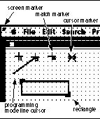
The internal state of Triggers includes markers, rectangles, and flags. A marker stores the coordinates of a point on the computer display. There are several special purpose markers (Figure 7). The cursor marker always points to the current mouse location. The screen marker always points to the upper left corner of the computer display. The match marker points to where the last pixel pattern search found the pixel pattern. A rectangle is a pair of markers representing the upper-left and lower-right corners of a rectangular area of the computer display. Markers and rectangles are placed to specify pixel pattern tests. Flags are Boolean true/false values that allow a Triggers program to remember the truth of conditions that are no longer reflected in the display content, or that certain actions have already been taken.
The condition steps of a trigger test the value of flags, test for pixel patterns on the computer display, and move the markers necessary to specify the pixel pattern tests. One type of pixel pattern test is the specific location match. If the specified rectangular pattern appears at a specific location, then the test succeeds, otherwise it fails. The specific location is specified as a constant offset from one of the markers.
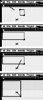
The only other type of pixel pattern test is the pixel pattern search. This test searches a given rectangular area on the computer display for a rectangular pattern. The bounds of the rectangular area are specified by setting the upper-left and the lower-right corner of a rectangle a constant offset from markers. A different marker may be used for each corner (Figure 8). The search area is scanned from left to right and top to bottom until the first instance matching the pattern is found. If a match is found, the match marker is placed there and the test succeeds. Otherwise, the test fails. The mouse cursor is hidden during both types of pixel pattern tests so that the pixels representing the mouse cursor do not interfere.
Several tests may appear among the condition steps of a trigger. If several steps are executed before one fails, then all marker locations are reset to where they were before the trigger was tried. This ensures that only a trigger that fires changes the state of the computer. If all steps succeed then the markers are left in place so that the action steps may be specified relative to the results of pixel pattern searches.
The action steps change the state of the computer by simulating user actions and setting internal flags. Three types of user actions may be simulated. One is the clicking or double clicking of the mouse at a location specified by a constant offset from one of the markers. The second is the linear mouse drag which is specified as a mouse down at one location and mouse up at another location. The mouse is dragged in a straight line between the two locations which are both specified as a constant offset from markers. The third simulated user action is a keypress. Because these steps might irreversibly change the state of the computer, they may only appear in the action steps of a trigger.
A Triggers program is invoked by pressing a combination of keys on the Macintosh keyboard. A running Triggers program continuously tries triggers until either a special stop action is executed or the user explicitly stops the Triggers program by pressing a special key on the keyboard. For debugging, there is a one pass invocation that tries each trigger in turn until one fires or all have been tried.
One can imagine many ways to extend Triggers' functionality. Patterns of shapes other than rectangles could be made possible by including wildcard pixels. The sequence of the condition steps make conjunctions of tests easy to implement, but a natural way to implement disjunctions or negations has yet to be provided. The internal storage should be enriched with integers, reals, strings, and pixel maps. Nonlinear drags should be possible. More expressive invocations could be supported. But even with limited functionality, Triggers is a remarkably useful programming system and proves the appropriateness of pixel-based data access in the examples that follow.

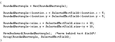
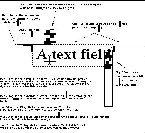
To automate this task, a programming system must somehow access the size and location of the text field. An algorithm in C might have the basic structure shown in Figure 10. A device-level algorithm, however, must simulate how the user could algorithmically accomplish the task manually. MacDraw II does not allow the user to specify the size of a rounded rectangle by inputting a number, so the device-level algorithm must create the rectangle by selecting the rounded rectangle tool and dragging the mouse the correct distance. All that is needed is a reliable way to determine the size and location of the text field in mouse coordinates through pattern matching on the pixel representation. MacDraw II conveniently places a gray bounding box around a selected text field, so a device-level algorithm can determine the size and location by searching for pieces of this box. The complete device-level algorithm for wrapping the rounded rectangle around the text field and grouping the two together is shown in Figure 14. The algorithm assumes that the text field is selected and that the mouse cursor is inside and close to the upper-left corner of the text field.
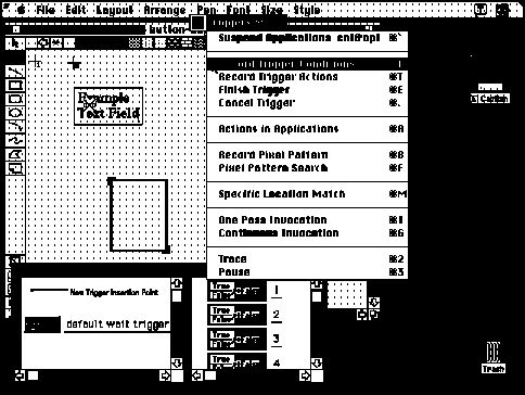
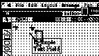
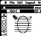
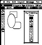
This device-level algorithm can be verified with Triggers by recording one trigger with steps 1-5 as conditions and steps 6-10 as actions so that the trigger will not create the rounded rectangle unless all sides of the text field bounding box are found. To start recording, the user first selects an example text field and places the mouse cursor inside the text field as required by the algorithm. The user then toggles into programming mode by pressing the control and option keys simultaneously. At this point the screen is covered with a desktop blanket and special widgets and windows that float above all the Macintosh windows. The desktop blanket clearly indicates that the Macintosh applications are suspended and that the user is now interacting with Triggers. The cursor marker remembers the location of the mouse cursor so that the mouse is free for interactions with Triggers. The user selects Record Trigger Conditions from the Triggers Menu as shown in Figure 1 at the start of this chapter.
Figure 10. A plausible C algorithm for wrapping a rounded rectangle around a text field in MacDraw II.
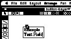
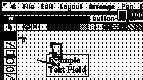
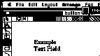
Marker placements, rectangle corner placements, mouse clicks, and mouse drags are all recorded as constant offsets from whatever marker is currently the base marker. Since the search of step 1 is in relation to the cursor, the user double clicks on the cursor marker to make it the base marker. The line cursor extends from the base marker and follows the mouse location giving clear indication of which marker the steps are recorded relative to. The user demonstrates step 1 of the algorithm by dragging the corners of the rectangle to mark a search area above the cursor (Figure 11). The pixel pattern is then specified by selecting Record Pixel Pattern from the Triggers Menu and placing the selection rectangle around a small part of the text field bounding box. The desktop blanket disappears so that the pattern being selected is not obscured (Figure 12). The search is completed by selecting Pixel Pattern Search from the Triggers Menu. The match marker now rests on the top of the bounding box (Figure 13).
The search for step 2 is specified relative to where the last search found the pattern, so the user now double clicks on the match marker to make it the base marker. A new search area is specified by placing the rectangle so that it extends below and left of the previous match. The rest of step 2 is completed much like step 1.
Step 3 of the algorithm is recorded by dragging marker#1 to an arbitrary location near the match marker, which was updated by the search of step 2 (Figure 15). Steps 4 and 5 are recorded similar to the search in step 2. At this point marker#1 effectively marks the upper left of the text field and the match marker marks the lower right (Figure 16). The user is now ready to record the action steps of the trigger and selects Record Trigger Actions from the Triggers Menu.
Step 6 is recorded by double clicking on the screen marker to make it the base marker. Then Record Actions in Applications is chosen from the Triggers Menu and the desktop blanket is removed indicating that MacDraw II will respond to mouse clicks. The user simply clicks once on the rounded rectangle tool (Figure 17), and then clicks on the Triggers Menu to reactivate the desktop blanket.
The mouse down in step 7 is relative to marker#1 so the user double clicks on it to make it the base marker. The mouse up should be relative to the match marker, so the user triple clicks on the match marker making it the mouse up marker. As usual, the line cursor follows the mouse from the base marker, but now an additional line follows from the mouse up marker. Record Actions in Applications is selected again and the user demonstrates the mouse drag that creates the rounded rectangle of the proper size and location. The user continues to demonstrate steps 8, 9, and 10 in macro-like fashion. The user completes the trigger by selecting Finish Trigger from the Triggers Menu.
Using the current interface all these steps take less than three minutes to record, not including the time to formulate these steps. If the user now creates a new text field, places the cursor inside the text field bounding box, and runs the Triggers program, the field is wrapped by and grouped with a rounded rectangle in less than two seconds.
It is interesting to consider how one might automate this task in C. First one might consider what raw information the programming system could optimistically access. One could easily imagine that the end point and perhaps the length of the line could be accessible. The point where the line intersects another object is much less likely to exist. If the program relies on a protocol like Apple Events, information like the point of intersection would be unlikely to be included. The C algorithm would probably have to search among the objects and compute the intersection points explicitly using computational geometry. Each type of object (rectangles, lines, polygons, ovals, etc.) would be a special case, making the algorithm complicated.
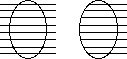
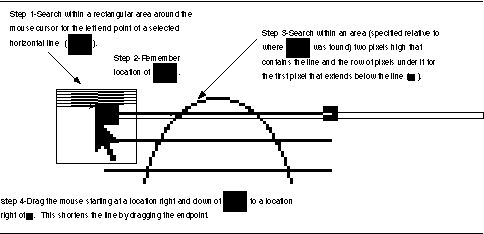
In contrast, the intersection point is clearly represented on the screen in pixel form. The user can easily, although tediously, do this task manually without using computational geometry by looking at the pixel representation. In fact, the screen buffer is probably the only place in the computer where the information is explicitly represented! Figure 21 shows a device-level algorithm that automates this task which works for shortening the left end of a horizontal line. The algorithm is so simple that a general algorithm that handled any end point of vertical and horizontal lines could be easily constructed by combining this algorithm with ones for the other three cases.
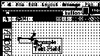
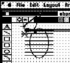
The four step algorithm in Figure 21 can be verified with Triggers by creating one trigger that continually searches for the left end of a selected horizontal line. Figure 19 shows the specification of the pixel pattern for the search of step 1. Figure 20 shows the state of recording the algorithm after step 3 and shows the need for a zoom feature which Triggers does not currently have. Marker#1 is the base marker as indicated by the line cursor extending from it. The match marker is the mouse up marker as indicated by the narrower line. Once the user has finished recording the trigger, the Triggers program can be invoked to run continuously. As the user selects each line, the trigger automatically fires and shortens the line.
A programming system that can read pixels on the screen opens up opportunities for novel ways of invoking new automation. The previous Triggers program shows a small example of this in the way the user can select the lines and have the automation invoked automatically. Another example we have implemented is to create floating tool palettes in applications that do not already have them. A bit mapped image of the tool palette can be placed in MacDraw II and triggers can be set up to see if the mouse cursor is above these phantom tools. Clicking on the bitmap image causes a selection which can easily be detected by a pixel pattern search. Another pixel pattern search can determine which tool the cursor is above and the trigger actions can then automatically select the corresponding real tool and return the mouse to the phantom tool palette, thus simulating a real floating menu (Figure 22).
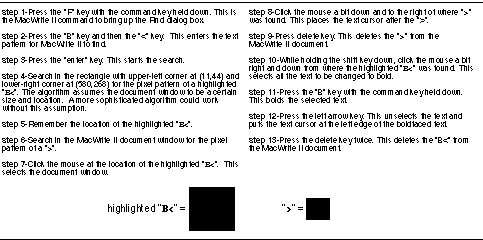
a search and replace feature that can change the style of all occurrences of a certain string of text, but it has no way to search for all text that is between "B<" and ">".
A device-level algorithm that automates this task is shown in Figure 23. This algorithm can be implemented with two triggers. The first trigger manipulates MacWrite II into searching for the text string "B<" as specified by steps 1-3 of the algorithm. The second trigger waits for the completion of a successful search, finds the pixel representations of the highlighted "B<" and the ">" on the computer display, and then uses this information to bold the enclosed text and remove "B<" and ">" as specified in steps 4-13.
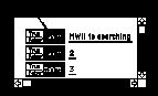
After loading the document into MacWrite II, the user toggles into programming mode and starts recording the trigger condition steps of the first trigger. A flag is needed to insure that this trigger will not repeatedly fire so the user clicks on one of the flags to record that the flag should be FALSE (Figure 24). The user then records steps 1-3 into the action steps of the trigger and then one additional step that changes the state of the flag to TRUE.
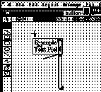
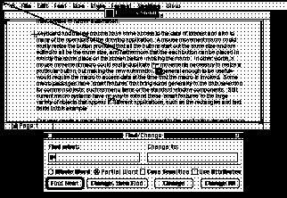
Steps 7-13 of the algorithm depend on steps 4-6 being successful, so steps 4-6 appear as condition steps in the second trigger. The user starts recording the second trigger by recording that the flag should be TRUE as the first step. Steps 4-6 are recorded using direct manipulation just as in the previous examples, and marker#1 is used to remember the location as required by step 5. Figure 25 shows the match marker after the search of step 4 has been recorded. The user records steps 7-13 taking special care that the base marker is correctly set for each action. The user records a final action step that sets the flag back to FALSE and selects Finish Trigger from the Triggers Menu. Once the user invokes the Triggers program, all instances of text in the file surrounded by "B<" and ">" are changed to bold.
Figure 25. The match marker pointing to where MacWrite II found "B<".
Another limitation is that device level algorithms run less efficiently than algorithms that use higher-level data structures. User interface device i/o is often optimized to be only fast enough to account for human speed. Thus the device i/o bottlenecks can limit the potential speed gains sought from automating. Information is not represented in its most compact form at the device level, which leads to more inefficiencies. For example a character that takes up one byte of storage at the application level can take up 100 or more bytes in a color pixel representation.
Device-level programs often depend on superficial user interface features, which makes them fragile. For example, reassigning the meaning of command keys, changing font size, or reordering the tools on a tool palette could break an existing device-level program. This complicates the creation of algorithms that are robust enough to be archived or shared. Thus the opportunities appropriate for device-level techniques are mostly limited to end-user programming where the benefits more than offset this limitation.
A fourth limitation is that there is only one set of user interface devices. One consequence of this is that the user and the programming system must share the devices. The programming system must have full control of the devices while doing its tasks and thus it is difficult for automated tasks to be performed in the background. All the intermediate side effects will also be displayed, which can be an unnecessary distraction to the user.
One of the keys to Triggers' success is that programs can be specified by demonstration. As shown in Figure 6, device-level algorithms can be cryptic when viewed in their raw form. Programming by demonstration overcomes this limitation by allowing users to specify their programs in a context that tells the users precisely what high-level actions correspond to the low-level representation. For example, a user does not have to know the pixel coordinates of the rounded rectangle tool to automate the "wrapping in rounded rectangle" example presented earlier. The user merely demonstrates the mouse click and the programming system records the coordinates automatically.
Currently, Triggers' user interface allows users to create programs by demonstration. Future versions of Triggers will improve this interface and extend the demonstrational style to the debugging and editing of programs. The result will be a programming system that allows users to visually create, verify, and edit programs that perform meaningful automation in their existing applications.
Intended users: Researchers
Feedback about capabilities and inferences:
When running, Triggers optionally highlights the areas of the screen being searched for pixel patterns. Execution can be paused during any pixel pattern test for inspection. Highlighting icons gives a visual trace of program execution.
Program constructs: The condition-action rules are implicit conditionals. Continuous trying of the rules is an implicit while loop. Boolean flags within rules allow for more complex program constructs.
Macintosh. Implemented in 12,000 source lines of C on top of the Think C class library, 1991.
Table of Contents Watch What I Do